The construction is slightly different in that instead of having a distributor that properly distributes refrigerant to all the coils circuits a liquid overfeed coil has a supply header with an orifice welded into each tap tube. The unit may have a quantity of two circuits at 5 tons each and the evaporator coil will have two circuits as well.
Understanding Coil Circuiting With A Simple Guide Campbell Sevey
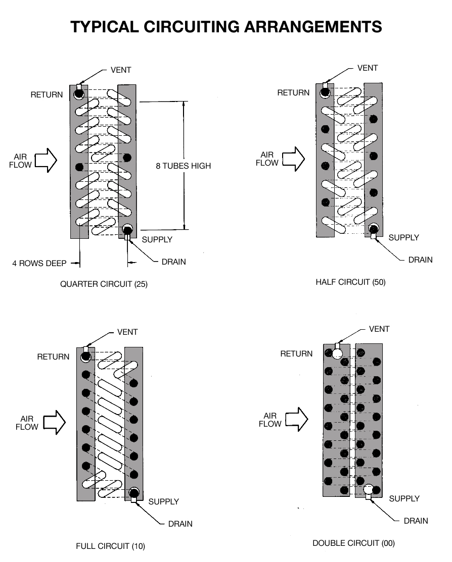
There are three standard ways to design direct-expansion coils with multiple distributors and thermostatic-expansion valves called split circuits figure 1.

. These orifices are largest at the. This means that the refrigerant must be heated 12 o F above the saturated suction temperature SST. Refrigerant-Refrigerant inlet refrigerant flow rate.
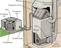
Focuses on Methods to design the cooling and dehumidifying coil or Direct Expansion evaporator coil. Evaporator coils are designed and engineered for effi cient operation with all refrigerants. An evaporator coil receives the refrigerant through an expansion valve and into a distributor barrel.
Evaporator more liquid than can be completely boiled off through the coil. Unique interlaced circuiting options assure uniform refrigerant distribution over the entire face area of the coil. A loop of suitable pipe containing the refrigerant and lubricant is put in direct contact with the ground or water body.
Cooling coil which is used in Evaporator of VARC System for given cooling load. Evaporator Coils DCON The heart of our air heat exchangers is the finned coil built up from a circuit of interconnected tube serpentines and hydrophilic anti-corrosive coated fins to increase the heat exchanging surface. Like the condensing unit they too are plotted as capacity versus SST.
DX ground-coupled HPs use refrigerant in DX flooded or recirculation evaporator circuits for the ground pipe coils. Out tube heat transfer enhancement. To refrigerant mass flow through the evaporator pressure drop must.
Evaporator coil circuit design Written By tienmccalebb33404 Friday April 8 2022 Add Comment Edit. Governing equations and methodology The sizing of cooling coil requires solving the two energy equations of the air. It is essential that the heat load on all circuits of the evaporator coil be the same.
372 Heat Exchangers Basics Design Applications Where k g l minimum free-flow air area m 2 _ mass flow rate of air through the cooling coil kgs J _ dynamic viscosity of air kgms _ thermal conductivity of air Wm. The unit may be tagged as a 10-ton unit and the components will all be sized for 10 tons. The process consists of designing a part using the calculation and various other parameters.
The coil configuration selected consisted in a parallel-counter current combination of two circuits and the simultaneous presence of subcooled liquid phase change and superheated vapour. The barrel is sized to fit the. Typical evaporator coil performance curve Coil curves are fixed.
However this will increases the pressure drop in the refrigerant side and performances of the coil and system are adversely affected. In tube pressure drop enlargement. C m outside diameter m 5.
In the design of evaporator coils increasing refrigerant mass velocity can enhance the heat transfer of an evaporator coil. Evaporator coil circuit design Written By tienmccalebb33404 Friday April 8 2022 Add Comment Edit. Direct-expansion evaporators typically are used in low temperature refrigeration applications to cool and sometimes dehumidify air.
Providing insights for todays HVAC system designer Trane Engineers Newslettervolume 484 3. An attempt is made to investigate the possibility of improving the coil. Abstract- This Paper consist of the detail design process of a cooling coil which is used in Evaporator of VARC System for given cooling load.
MATERIAL SELECTION AND GEOMETRY Aluminum Copper are preferred material has it is good conductor of heat Round seamless. Wide fin spacing availability reduces the affect of frost build up on low temperature applications. HEATCRAFT EVAPORATOR COILS Single dual or quad compressor circuits allow precise capacity control.
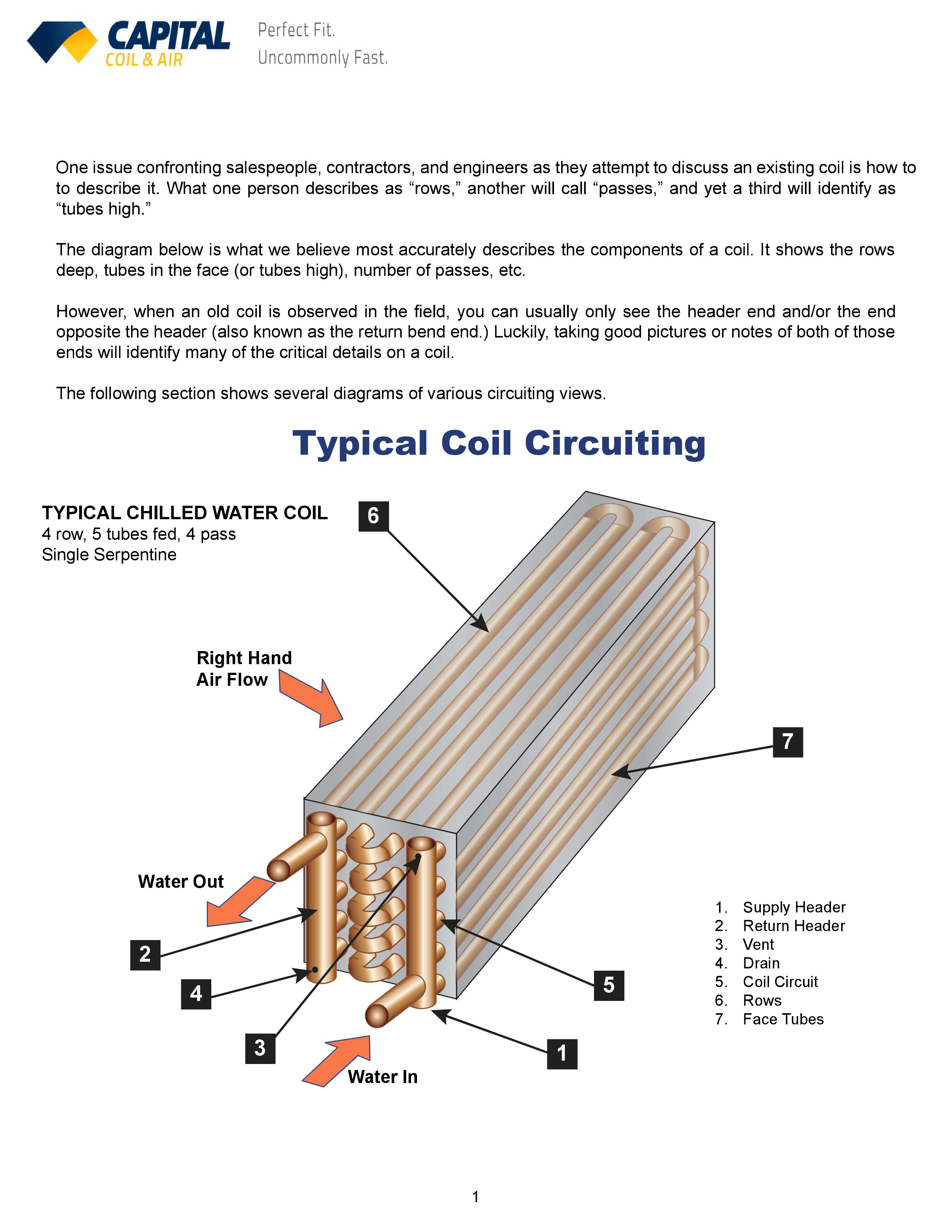
The heart of our air heat exchangers is the finned coil built up from a circuit of interconnected tube serpentines and hydrophilic anti-corrosive coated fins to. Ideally the tube circuiting in an evaporator coil are designed to be identical to each other for consistent pressure drop and flash temperature with the first and last tube of the circuit on or near the warmest air side of the coil. A coil WILL operate on its coil curve if the air conditions remain constant as the SST changes.
Design is made on real world scenario to enhance the optimization in sense of very aspect. The developed tool was then used to study a typical CO 2 evaporator coil commonly used in low temperature supermarkets applications. Design of Evaporator Cooling Coil for Cooling Load Abhijeet Samal1 Mechanical Engineering BMS College of EngineeringBengaluru.
Mostly gas and other circuits the liquid. Circuits numberNBcircuit per row. Knowledge there is not an existing distributed simulation model for the study of tube circuitry of evaporator coils.
The process consists of designing a part using th e calculation and. The ideal ratio of coil finned height to finned length is 12 to 13. Large capacity of the coil and compact rolls with a few lines of the tube designed widi more than one refrigerant circuit.
Fin style0Straight 1Slot 2Triangle wave 3Sine wave Tube material-1See notes 0Copper 1Steel 2Aluminum Fin material-1See notes 0Aluminum 1Copper 2Steel In tube heat transfer enhancement. Evaporator circuit of one of the refrigerant passage between the inlet and outlet connections of the evaporator. This degrades the heat transfer capabilities of the evaporator coil.
Design of Evaporator with CO2 Coolant Design of Evaporator with CO2 Coolant Bruce Nelson President Colmac Coil The selection process of the evaporators that operate in a system of refrigeration with CO2 is very similar to the selection of evaporators for ammonia.
The Difference Between Evaporator Coil Condenser Coil
Chilled Water Cooling Coils Circuiting Made Easy

Refrigeration Design 2017 07 01 Assembly

Refrigeration Design 2017 07 01 Assembly
Air Conditioner Evaporator Coil Cleaning

Schematic Of A Typical Refrigeration Evaporator Coil Download Scientific Diagram

Refrigerator And Freezer System Arrangements Refrigerator Troubleshooting D Refrigeration And Air Conditioning Air Conditioning Design Air Conditioner Repair

Evaporator Coil Air Conditioners Quality Hvac 101
0 comments
Post a Comment